Lab 3: ToF Sensors + I2C Addressing
This lab focuses on scanning the I2C bus, configuring two VL53L1X Time of Flight sensors with unique addresses, selecting a ranging mode, and evaluating range, accuracy, repeatability, and ranging time. Data is streamed over Bluetooth while running ToF + IMU in parallel.
1. Prelab
I2C Addresses
- Time of Flight (ToF) Sensor 1:
0x14 - Time of Flight (ToF) Sensor 2:
0x29 - Inertial Measurement Unit (IMU):
0x69
Addressing Workflow
- Connect both ToF sensors to the I2C bus.
- Use SHUT/XSHUT to turn one ToF sensor off.
- Initialize the active ToF sensor and assign it a new address (e.g.,
0x29). - Turn the second ToF sensor back on.
- Initialize the second sensor at its new address and read both sensors in the loop.
Sensor Placement on the Robot
The most important placements for ToF sensors are the front and back of the robot. The robot mainly moves forward/backward and turns, so forward/back obstacle detection is critical. The robot may still miss obstacles above/below it, and certain side-angle obstacles depending on placement.
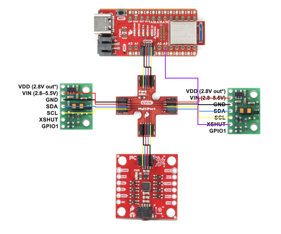
Circuit Diagram
Here is my circuit diagram showing the Artemis, two VL53L1X ToF sensors, and the IMU. Both ToF sensors are connected to the same I2C bus, with one sensor’s SHUT pin used for address reassignment.
2. Lab Tasks
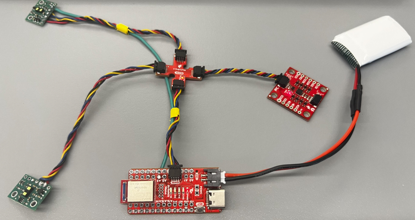
Hardware Setup + I2C Scan
To use two VL53L1X sensors at once, at least one sensor needs a unique I2C address. Both sensors start with the same default address, so I used the SHUT (XSHUT) pin to temporarily disable one sensor and then reassigned the other.
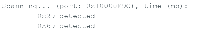
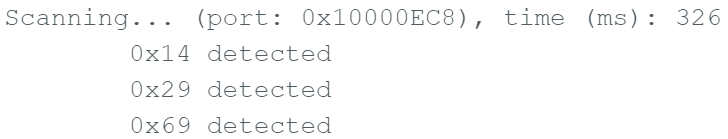
I2C Address Summary
I initially detected 0x29 (default ToF address) and 0x69 (IMU). After re-addressing, I assigned 0x29 to one ToF sensor and the other ToF sensor appeared at 0x14.
Setup / Addressing Sensors Code
SFEVL53L1X distanceSensor1;
SFEVL53L1X distanceSensor2(Wire, XSHUT_PIN, INTERRUPT_PIN); // Contains interrupt and shutoff

void setup(void)
{
  Wire.begin();
  Serial.begin(115200);

  // Set GPIO
  pinMode(XSHUT_PIN, OUTPUT);

  // Turn off one of the sensors
  digitalWrite(XSHUT_PIN, LOW);
  delay(10);

  // Change I2C address
  distanceSensor2.setI2CAddress(0x29);

  // Turn the sensor back on
  digitalWrite(XSHUT_PIN, HIGH);
  delay(10);

  if (distanceSensor1.begin() != 0) {
    Serial.println("Sensor 1 failed to begin. Please check wiring. Freezing...");
    while (1) {}
  }

  if (distanceSensor2.begin() != 0) {
    Serial.println("Sensor 2 failed to begin. Please check wiring. Freezing...");
    while (1) {}
  }

  Serial.println("All Sensors Are Online!");
}
3. ToF Modes (Short, Medium, Long)
Pros / Cons and Mode Selection
The VL53L1X supports multiple ranging modes that trade off speed, range, and robustness under different lighting conditions.
Short Mode
- Best for close range detection (~1–1.3 m typical)
- Fast updates (good for high-speed feedback)
- Low power
- Better performance in high ambient light
- Reduced motion blur
Tradeoff: lower max range than medium/long mode.
Medium Mode
(Only available with the Pololu VL53L1X library)
- Balanced range and speed
- Moderate accuracy
- Acceptable noise rejection
Tradeoff: slower than short mode and less range than long mode.
Long Mode
- Longest range
- Better sensitivity for weak returns
- Good for detecting far obstacles
Tradeoffs: slower updates, higher power, more sensitive to ambient IR noise, and more motion blur on fast robots.
Chosen Mode for This Robot
I chose Short Mode because the robot needs fast feedback for high-speed motion. In class, we focus on moving the robot quickly, and faster updates are more important than long-range detection for this use case.
Short Mode Code
distanceSensor1.setDistanceModeShort();
distanceSensor2.setDistanceModeShort();
4. Test the Chosen Mode (Short Mode)
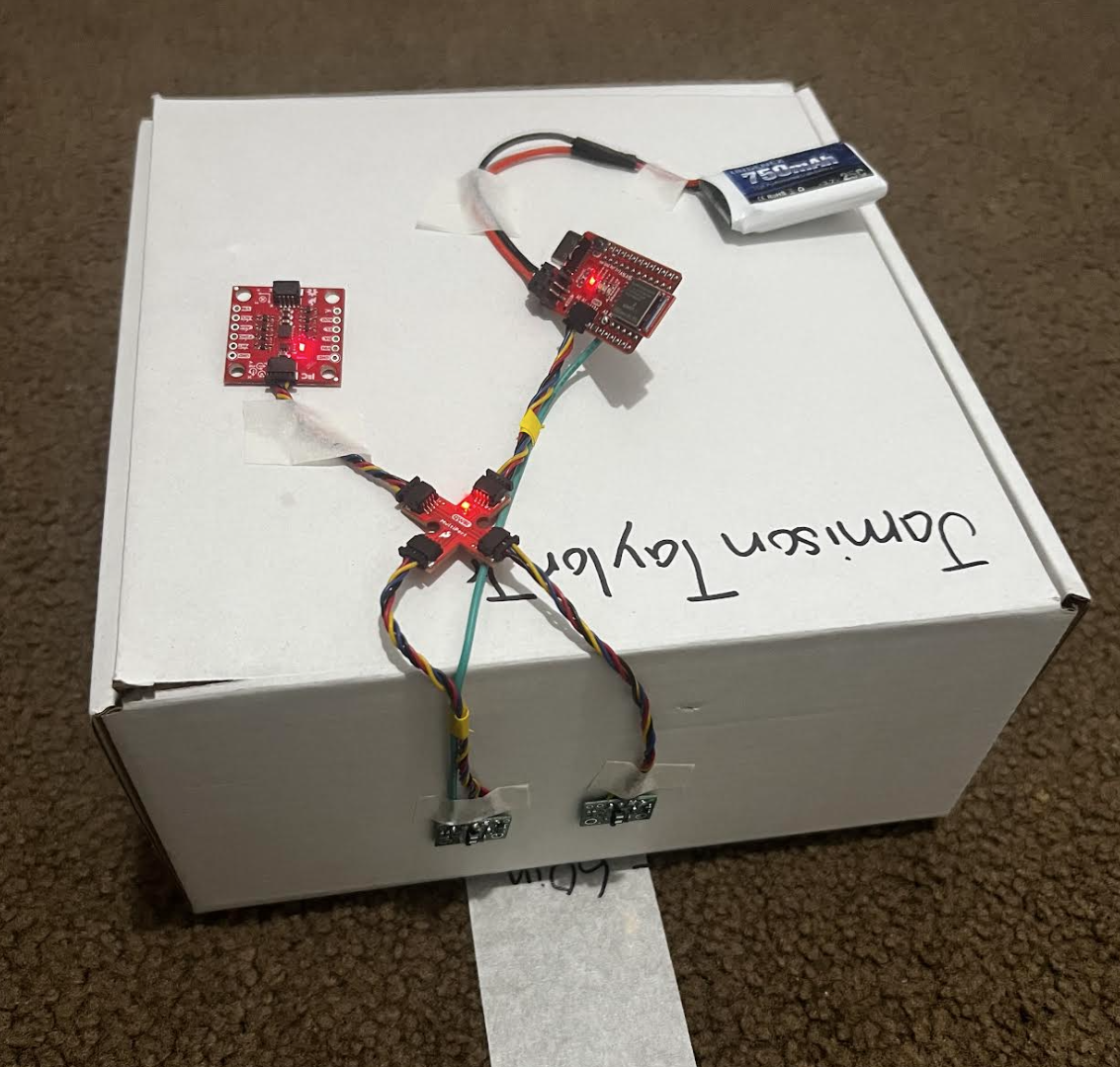
Experiment Setup
I taped both ToF sensors to a box and faced them toward a wall. Over Bluetooth, I streamed ToF distance readings while collecting IMU data in parallel. This helped me evaluate range, accuracy, repeatability, and ranging time.
Loop / Distance Collection Code
void loop(void)
{
distanceSensor1.startRanging();
distanceSensor2.startRanging();
while (!distanceSensor1.checkForDataReady()) { delay(1); }
while (!distanceSensor2.checkForDataReady()) { delay(1); }
int distance1 = distanceSensor1.getDistance();
int distance2 = distanceSensor2.getDistance();
distanceSensor1.clearInterrupt();
distanceSensor2.clearInterrupt();
distanceSensor1.stopRanging();
distanceSensor2.stopRanging();
Serial.print("Distance1(mm): ");
Serial.print(distance1);
Serial.print(" Distance2(mm): ");
Serial.print(distance2);
float distanceInches1 = distance1 * 0.0393701;
float distanceFeet1 = distanceInches1 / 12.0;
float distanceInches2 = distance2 * 0.0393701;
float distanceFeet2 = distanceInches2 / 12.0;
Serial.print("\tDistance1(ft): ");
Serial.print(distanceFeet1, 2);
Serial.print("\tDistance2(ft): ");
Serial.print(distanceFeet2, 2);
Serial.println();
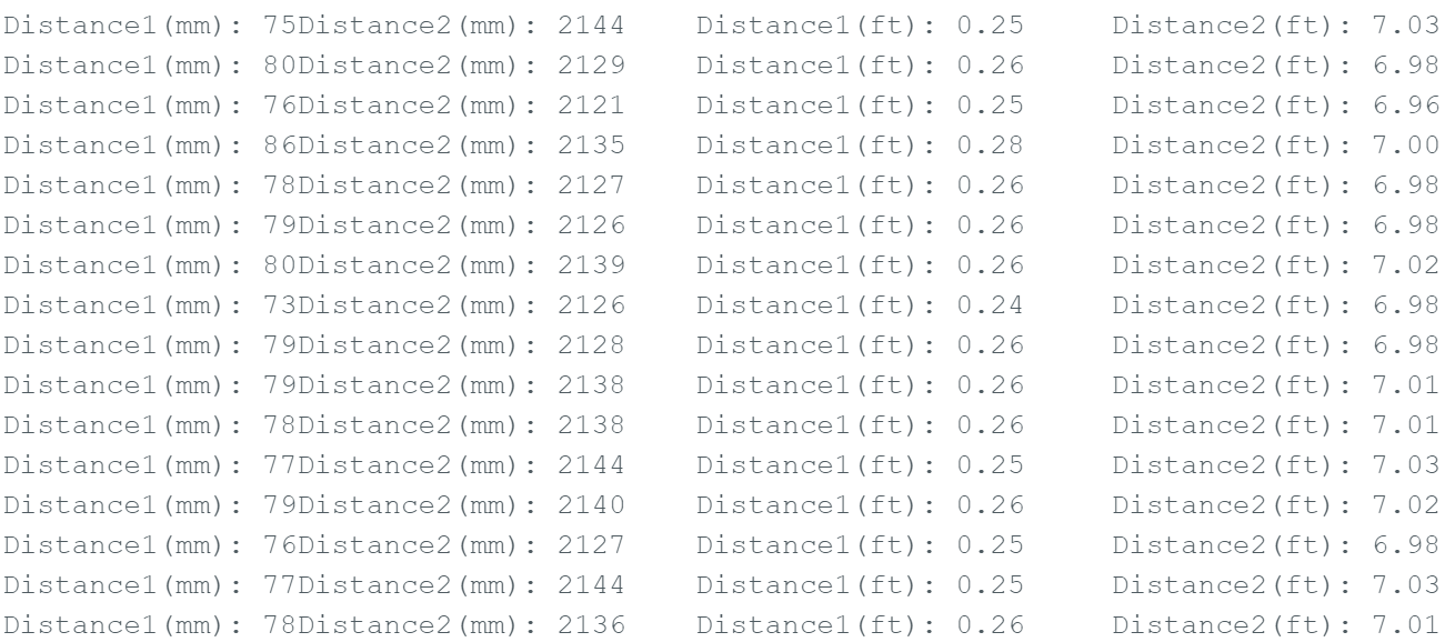
}Results
Range
In short mode, the sensors were most reliable within about 0–12 inches (1 foot). Past 1 foot, the data became much less consistent. I also tested with extra lighting aimed into the sensor path and saw similar results.
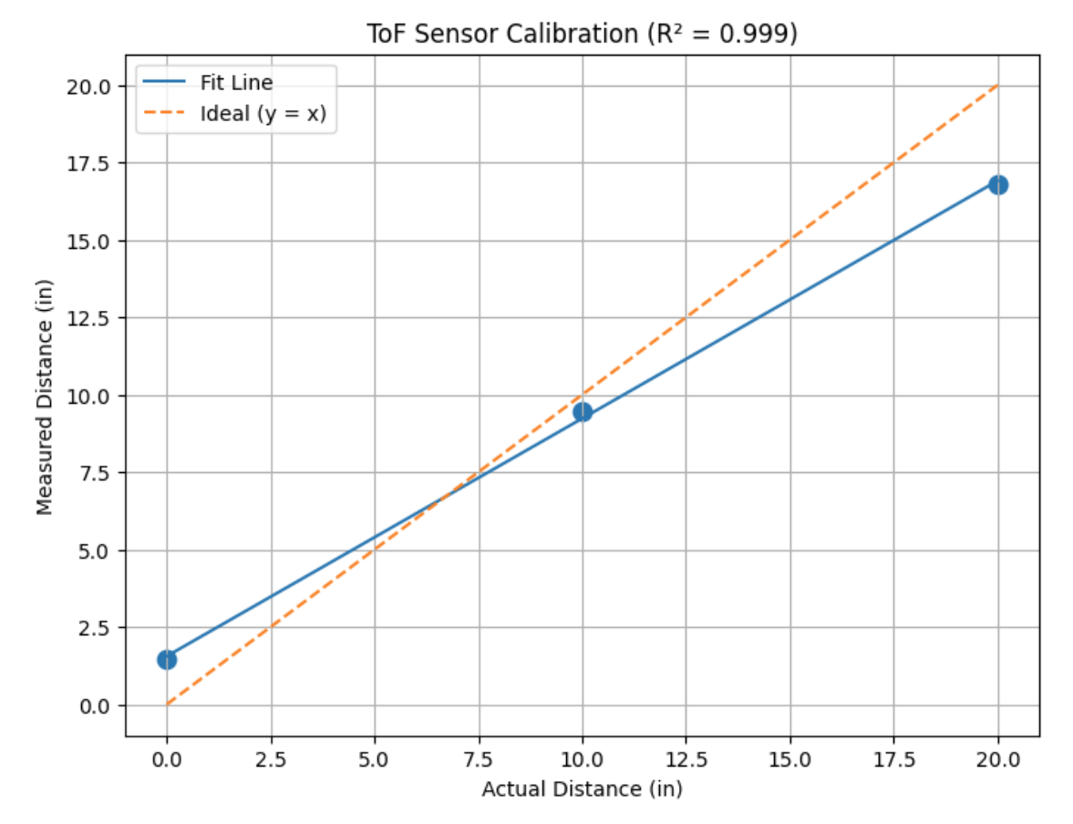
Accuracy
Within 0–12 inches, the readings were reasonably accurate. Any small differences between measured and true distance were most likely due to human measurement error. Beyond 1 foot, accuracy decreased significantly.
Repeatability
Within the effective range, repeated measurements at the same distance produced consistent readings (good repeatability).
Ranging Time / Speed
I ran the program 500 times and it took 30.24 seconds total.
Ranging time = 30.24 s / 500 = 0.06048 s = 60.48 ms
This timing is slower because both ToF sensors + accelerometer + gyroscope were running at the same time, and data was being sent over Bluetooth.
Time vs Distance (2 Sensors)
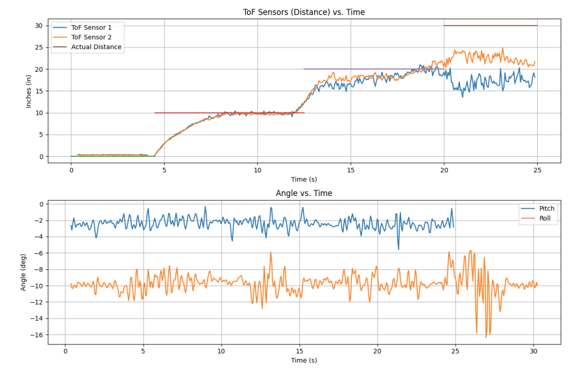
5. Infrared Transmission + Surface Sensitivity
Many distance sensors use infrared (IR) light. They send out IR and measure how much (or how fast) the light comes back after reflecting off a surface. Because of that, the material and lighting in the room can change the sensor’s performance.
How IR Distance Sensing Works
- The sensor emits IR light toward an object.
- The object reflects some IR back to the sensor.
- Stronger reflections usually give more stable readings.
- Bright light (especially sunlight) can add IR noise.
Surface Sensitivity (Color + Texture)
- Light / bright surfaces reflect more IR → better readings.
- Dark surfaces absorb more IR → noisier / shorter range.
- Smooth surfaces reflect more consistently.
- Rough or angled surfaces scatter IR → less reliable distance.
In my ToF testing, I was also able to see what environment works best for the sensors. I ran a small experiment to compare readings at 4.5 inches in different conditions: good lighting on a white wall, a black plastic plate (dark surface), a blue bag (colored surface), and a darker setup where I used the blue bag to cast a shadow on the sensors and wall. The graph below shows the results.
ToF Environment Testing
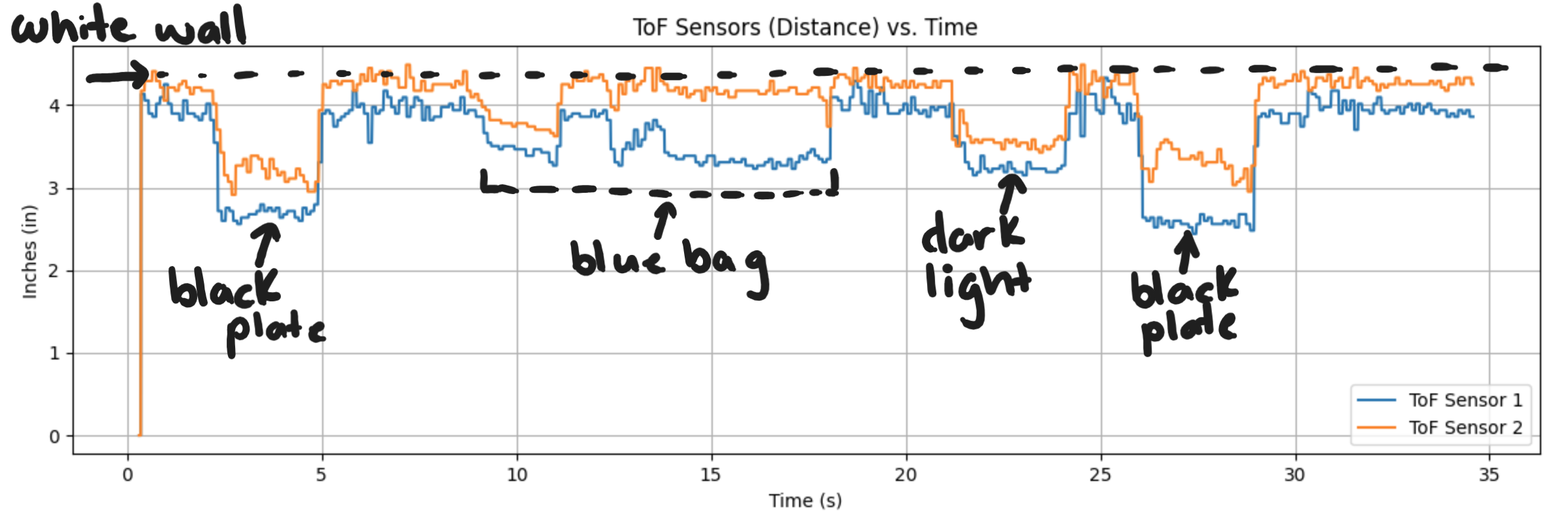
What This Means for My Robot
The ToF sensors worked best when the target was flat and light-colored. Readings became less consistent on darker or angled surfaces, and performance can drop in bright lighting.
6. ToF Sensor Speed (Code Snippet)
How I Measured Timing
To make sure the code could execute as fast as possible—and to prevent the sensors from forcing the program to hang while waiting for new measurements—I made a few changes:
-
Removed blocking while loops: I eliminated
while (!distanceSensor.checkForDataReady())statements so the program no longer stalls waiting for new sensor data. - Started/stopped ranging less often: Continuously stopping and restarting the sensors increases measurement latency and reduces loop speed.
-
Added a high-resolution timestamp: I created a constant 32-bit unsigned integer
t_usset equal tomicros(). Printing it let me see how quickly the loop ran. -
Implemented non-blocking sensor checks: I wrapped
getDistance()andclearInterrupt()calls inside anif (checkForDataReady())statement. That way, new distance values are only read when available, and the loop continues running otherwise.
With these changes, I was able to run the loop 500 times in about 3.747 seconds. So now my code runs at 7.5 ms per loop, which is much faster than the previous 60 ms per loop I had before.
Timing Code
float distance1_in = NAN;
float distance2_in = NAN;
ToF_Sensor_1.startRanging();
ToF_Sensor_2.startRanging();
int count = 0;
for (int i = 0; i < Acc_length; i++) { // change Acc_length later
const uint32_t t_us = micros();
Serial.println(t_us);
count++;
if (ToF_Sensor_1.checkForDataReady()) {
int distance1 = ToF_Sensor_1.getDistance();
ToF_Sensor_1.clearInterrupt();
distance1_in = distance1 * 0.0393701f;
Serial.print("\tD1(in): ");
Serial.print(distance1_in, 2);
}
if (ToF_Sensor_2.checkForDataReady()) {
int distance2 = ToF_Sensor_2.getDistance();
ToF_Sensor_2.clearInterrupt();
distance2_in = distance2 * 0.0393701f;
Serial.print("\tD2(in): ");
Serial.println(distance2_in, 2);
}
Tof1_in[i] = distance1_in;
Tof2_in[i] = distance2_in;
}
ToF_Sensor_1.stopRanging();
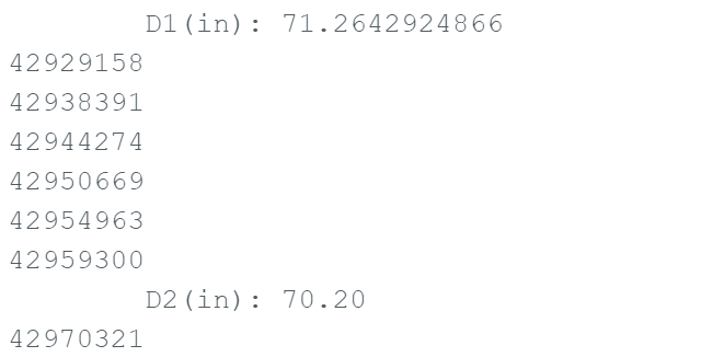
ToF_Sensor_2.stopRanging();Arduino Output
7. Resources
SparkFun VL53L1X Library
Used for sensor initialization, ranging mode configuration, and reading distance values.
Student Page
I used Ethan Sarpong’s Spring 2025 website to understand I2C scanning, addressing, and code execution.
ChatGPT
Helped clean up and format the lab write-up into a consistent webpage structure.